Looking At the Effect of Pallet Fastener Quality on Pallet Durability
Figure 0 - types of nails

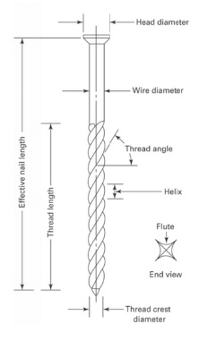
There are three common types of nails that are used in pallet construction: helically threaded, annularly threaded, and plain shank (Figure 1). Plain shank nails are regular nails with a smooth shank. Helically threaded nails have continuous spiral threads along the shank. Annularly threaded nails have a series of rings along the shank that grip the wood and help to prevent the nail’s withdrawal. The effectiveness of pallet nails is dependent on a variety of parameters including head diameter, wire diameter, thread crest diameter, thread angle, helix, flute, thread length, and effective nail length (Figure 2).
Figure 1. Common nail types used for pallet construction: (top to bottom) helically threaded nails, annularly threaded nails, and plain-shank nails.
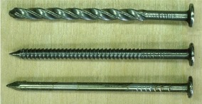
Figure 2. The anatomy of nails used in fasteners.
The Uniform Standard for Wood Pallets (NWPCA, 2014) lays out guidelines for nailing pallets. Nails used must penetrate the pallets’ block or stringer to at least a certain depth. For deckboards with thicknesses over ½ in., nails must penetrate at least 1¼ in., while for deckboards with thicknesses of ½ in. and under, nails must penetrate at least 1 in. The standard also defines the minimum number of nails that must be used per connection. For example, a minimum of two nails must be used for deckboards that are a width of 5¼ in. or less, and a minimum of three nails must be used for deckboards that are 5¼ in. to 7 in. wide. Nails must also be arranged in a way that minimizes the splitting of the wood and must have a minimum head-to-shank ratio of 2 (except for new, reusable pallets, which need to have a ratio of 2.25). This standard also defines minimum nail quality based on the fastener withdrawal resistance (FWI) and the fastener shear resistance (FSI). The minimum FWI is 65 for multiple-use pallets and 50 for limited-use pallets, and the minimum FSI is 55 for multiple-use pallets and 40 for single-use pallets.
Pallet Durability Modeling
In 1984, Wallin and Whitenack developed a model to determine when a pallet needs to be repaired. The model was built based on the data that was collected during the Pallet Exchange Program (PEP) study conducted by the USDA between 1967 and 1971 (Wallin et al., 1972). This three-year study analyzed 17 different types of stringer pallets that were exposed to 16 different handling environments. The data collected from this study were about pallets’ total number of handlings, locations of damages, number of damage occurrences, and relative severity of damage after each trip. This data allowed the authors to develop a classification system about the types and levels of damage a pallet endures. They came up with nine levels of damage severity. It was found that the optimal time to repair a pallet is when the damage severity level reaches 7 or higher.
Figure 3. Wallin and Whitenack's economic model to predict the overall durability of a pallet.
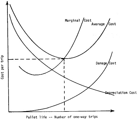
Wallin and Whitenack’s 1982 study also developed an economic model to predict the overall durability of a pallet (Figure 3). Their model calculates the maximum number of trips for which it makes economic sense to continue use of a pallet. The economic model is based on the average cost, damage costs, marginal cost, and depreciation cost. The average cost represents how much it will cost to use the pallet. This is a parabolic trend since the more times one uses a pallet the more the price goes down, but after a certain point the extra costs required to repair the pallet (damage costs) causes the user to start paying more per use. The damage costs represent the total amount spent in repairs to the pallet. It is a positive trend since damage costs are accumulated throughout a pallet’s lifespan. The marginal cost represents the value one gets out of a pallet if it’s used for one more trip. Finally, the depreciation cost represents the decreasing value of the pallet over its lifespan due to damage repairs.
This model utilizes the cost of damages to predict the overall durability of the pallet. To estimate the damage cost per trip, the model calculates the cost to repair each damage (C), which is calculated based on three variables (Equation 1). The first variable in the equation is the economic coefficient (c) which makes the cost calculated reflect the real-world cost of repairs. The second variable is the technical coefficient (b) and considers the design of the pallet. The last variable is the severity of the damage (S).
Equation 1: C = c bs
To calculate the total cost of damage (D) throughout the life of the pallet, this model uses the expected damage rate (r), the cost of repairing each damage (C), and the number of one-way trips the pallet will take (U).
Equation 2: D = C ( ( r + 1)u - 1 )
With this cost defined, one can easily determine if it makes economic sense to repair the pallet. According to Wallin and Whitenack, the pallet should only be repaired if the value of the pallet before the repair is greater than the total cost of damage (D).
To calculate the average cost of a pallet per trip (A), the model uses the total damage cost to a pallet during its life (D), the purchase price of the pallet (P), and the number of one-way trips the pallet can survive (U). Based on this analysis, the pallet should be used until the average cost per trip is the lowest is can reach (Figure 4).
Equation 3: A = ( D + P ) / U
The economic life of the pallet depends on the damage rate (r), the damage severity (s), and the economic factors (c) that influence the repair costs. Another study done by Wallin and Whitenack (1982b) describes an equation that relates the damage rate (r) to the damage severity (S) and the average number of trips survived.
These researchers developed the equations through a joint study that observed the damages to 877 pallets that represented 17 different pallet designs. The study found that damage severity (S) and damage rate (r) are strongly interdependent. This means that when a pallet receives damages more often, it is likely that the pallet will be damaged more severely.
Figure 4. Frequency of pallet damages compared with the severity of each damage incident.
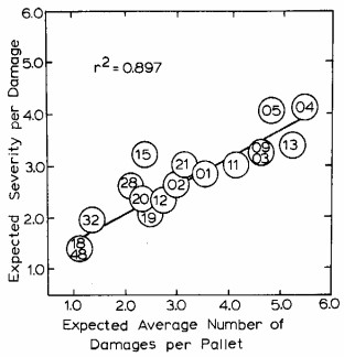
Another major finding of this study is that there is a correlation between the damage severity (S) and damage rate (r) to the lifespan of a pallet. This was discovered through an equation for expected cumulative damage (E(Z)). This equation uses the damage severity (S) and damage rate (r) to calculate the severity and frequency of damages after the initial damage to the pallet. A higher value indicates that a pallet is more fragile while a lower value indicates that a pallet is more durable. It was found that the greater the expected cumulative damage, the lower the frequency of damages and the less severe each incident of damage was. This led to the pallet surviving more handlings then before the initial damage (Figure 4) (Wallin and Whitenack, 1982b).
The damage rate (r) and damage severity (s) can be calculated using nine pallet damage factors, which are numerical evaluations of the pallet design.
Equation 4: r = [1+F(1)][1+F(2)][1+F(3)][1+F(4)][1+F(5)] * [1+R(1)][1+R(2)][1+R(3)][1+R(4)][.01]
Equation 5: S = [1+F(1)][1+F(2)][1+F(3)][1+F(4)][1+F(5)] * [1+R(4)/2][2.0]
The pallet damage factors in the above equations are as follows:
- F(1) = factor for fastener-withdrawal resistance
- F(2) = Factor for fastener-shear resistance
- F(3) = factor for connection-splitting resistance
- F(4) = factor for shook quality
- F(5) = factor for selective shook-quality placement
- R(1) = factor for flexural strength of stringers
- R(2) = factor for flexural strength of decks
- R(3) = factor for deck construction
- R(4) = factor for materials-handling environment
The two pallet damage factors that are directly influenced by the fasteners are the fastener withdrawal resistance F(1), and the fastener shear resistance F(2).
Fastener Withdrawal Resistance: F(1)
Figure 5. Showing fastener withdrawal causing pallet joint separation.

The F(1) damage factor is related to the resistance of the pallet joint to separation (Figure 5) (ASME, 1997). It is dependent on the fastener withdrawal resistance (FWR), which is a measure of the total withdrawal resistance of the fasteners in a pallet described in pounds per linear inch of penetration. The FWR is determined by the head pull through resistance (HPR) or fastener withdrawal resistance of a single fastener (FWRF), depending on which value is lower. For most nails, the FWRF is the governing factor and, thus, is the one used for this calculation. The FWRF is influenced by the specific gravity, the depth of penetration, the moisture content, and the fastener withdrawal index (FWI). FWI represents the relative resistance of a fastener against withdrawal compared to a base nail. The base nail has a wire diameter of 0.113 in., a thread crest of 0.133 in., nine helixes along the shank, 1.625 in. of threaded shank, and an average withdrawal resistance of 320 pounds per inch of penetration.
Equation 6: F W I = 221.24 W D [ 1 + 27.15 ( T D - W D ) ( H / T L ) ]
The FWI increases with increasing wire diameter, press out (which is the difference between thread-crest diameter [TD] and wire diameter [WD]), and the reduction of thread angle. The relationship between nail anatomy and a nail’s resistance to withdrawal has been thoroughly examined in a study performed by Wallin and Whitenack (1982c). They present the FWR as the fastener quality index (FQI). Their study looked at nails of varying measurements and found the FWR for each.
The study showed how changing wire diameter, press out, and thread angle can influence the FWR of the pallet joint (Figure 6). The thread angle is related to the other dimensions discussed previously. It was found that the thread crest diameter, number of helices, and thread length all play an important role in determining the overall withdrawal resistance of a nail.
Figure 6. Effect of nail parameters on the FQI or FWR. (Wallin and Whitenack, 1982c).
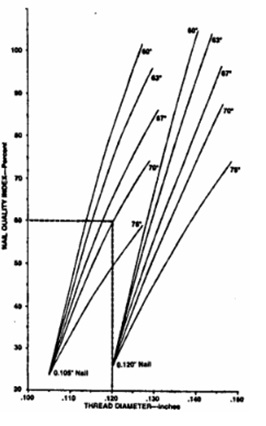
Wallin and Whitenack (1982c) also examined plain shank nails and staples. They isolated and observed the effects of wire diameter and how it affected the fasteners’ resistance to withdrawal. In short, the FWI is the comparative measure of how much force it will take for the fastener to withdraw from the wood joint. Figure 7 shows the FWI comparative to a base nail — meaning that an FWI of 60 indicates that the nail has 60% of the performance of the base nail. The base nail used here has a wire diameter of .113 in., thread crest of .133 in., 9 helixes along shank, 1.625 in. threaded shank, and an average withdrawal resistance of 320 pounds per square inch of penetration.
Figure 7. Minimum quality of driven fasteners comparative to a base nail.

Fastener Shear Resistance: F(2)
Figure 8. Showing fastener shearing causing pallet joint separation.

The F(2) damage factor is related to the resistance of the pallet joint against shear (MHI, 1997). It is dependent on the fastener shear resistance (FSR), which is the total shear resistance of fastener couples in pounds. The FSR is dependent on the fastener shear index (FSI), the oven-dry specific gravity, the thickness of deckboards, the moisture content at assembly, and the number of fastener couples per joint. The FSI represents the relative shear resistance of pallet fasteners compared to the base nail.
Equation 7: F S I = 263.26 W D1.5 / ( 3 M + 40 )
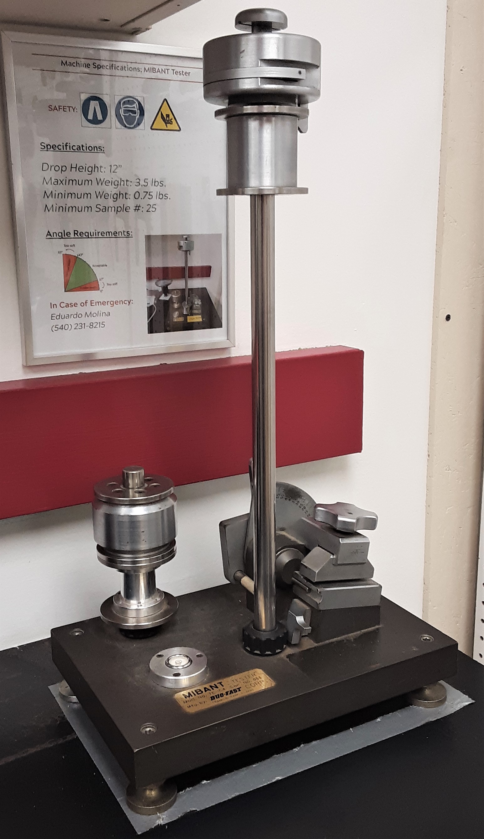
The FSI increases with increasing wire diameter. The FSI has an inverse relationship with the Morgan Impact Bend Angle Nail Test (MIBANT) angle. The MIBANT angle is determined by the MIBANT test (Figure 9), which drops a 3.5 lb. weight 15.4375 in. onto the head of a nail that is secured in a vice. The amount that the fastener bends is the MIBANT angle. The MIBANT test is basically a test of fastener impact resistance.
Figure 9. MIBANT tester
Example Provided
In order to illustrate the impact that fasteners have on pallet durability, we utilized the fastener durability input and fastener input analysis functions of the Best LoadTM pallet design software. This function allows the user to input all the details of multiple nails and compare their durability results. For this example, we compared 11.5-gauge bulk nails and 12.5-gauge collated nails in a standard GMA pallet. Figure 10 shows the different nail characteristics for these two nail types, including that the 11.5-gauge nail has better FSI and FWI values (67 and 55) compared to the 12.5-gauge nail (37 and 31).
| Nail Type: | 11.5 Gauge (bulk) |
12.5 Gauge (collated) |
|---|---|---|
| Wire Diameter (in.) | 0.112 | 0.099 |
| Thread Diameter (in.) | 0.122 | 0.104 |
| Head Diameter (in.) | 0.28 | 0.25 |
| Thread Length (in.) | 1.5 | 1.5 |
| Nail Length | 2 | 2 |
| Helix Count | 6.8 | 4.7 |
| MIBANT Angle | 36 | 60 |
| Thread Angle | 68 | 70 |
| Flute Count | 4 | 4 |
| FSI | 67 | 37 |
| FWI | 55 | 31 |
Figure 10. Characteristics of two differing nail types.
| Nail Type: | Cyles to 1st repair |
Cycles before replacement |
Relative Damage Rate |
Relative Damage Severity |
|---|---|---|---|---|
| 11.5 Gauge (bulk) | 2 | 4 | 0.193 | 7.117 |
| 12.5 Gauge (collated) | 1 | 2 | 0.281 | 10.343 |
Figure 11. Pallet durability based on different nail types used.
Pallets can be rated on their “relative damage rate,” which shows how rapidly the pallet will sustain damages from use. And they can be rated on their “relative damage severity,” which indicates how severe the damages are that the pallet sustains. The results in Figure 11 indicate that a pallet using 11.5-gauge bulk nails has significantly better durability performance than a pallet using 12.5-gauge nails. The pallet built with 11.5-gauge nails lasts twice as many trips before needing repairs as well as twice as many trips before requiring replacement. Also, the pallet with 11.5-gauge nails had lower relative damage rate values as well as lower relative damage severity. These values determine that the pallet made with 11.5-gauge nails is 85.6% more durable than the pallet made with 12.5-gauge nails.
Another article, by Stern (1979), also describes several relationships that have been explained here regarding nail characteristics and their durability. Stern found that more helices per thread length increases nails’ withdrawal resistance, and as the MIBANT angle decreases the shear resistance increases. His data further support the relationships already outlined between the nail characteristics and withdrawal and shear resistances.
Conclusions
- Better fasteners improve the durability of pallets, which saves time and money used to repair the pallet and better protects the product.
- Fastener withdrawal resistance and fastener shear resistance are major factors in pallet durability.
- Fastener withdrawal resistance is most affected by wire diameter, the difference between thread diameter and wire diameter, and the number of helices per thread length.
- Fastener shear resistance is most affected by the wire diameter.
- Using a 11.5-gauge bulk nail instead of a 12.5-gauge collated nail can improve pallet durability by 85.6% and double the life of the pallet.
References
- Material Handling Institute. (1997). MH1 – 2016 - Pallets, Slip Sheets, and Other Bases for Unit Loads. Retrieved from https://www.mhi.org/free/8956
- National Wooden Pallet and Container Association. (2014). Uniform Standard for Wood Pallets - 2014. Retrieved from https://cdn.ymaws.com/www.palletcentral.com/resource/collection/E8AADDDE-7CBA-4298-8341-C7F29D0C14FF/Uniform-Standard-for-Wood-Pallets-2014(REV).pdf
- Stern, E. G. (1979). Mechanical fastening of wood: two studies at VPI and SU. Forest Products Journal, 29(9), 52-54.
- Wallin, E. B., Strobel, J. J., Frost, R. E., and Stinson, P. R. (1972). PEP research study report. Unpublished manuscript, Northeastern Forest Experiment Station, Forest Products Marketing Laboratory. Princeton, WV.
- Wallin, E. B., and Whitenack, K. R. (1982). Durability analysis for wooden pallets and related structures. Unpublished manuscript, Northeastern Forest Experiment Station, Forest Science Laboratory. Princeton, WV.
- Wallin, E. B., and Whitenack, K. R. (1982b). Joint separation resistance - the first step in estimating pallet durability. Pallet Enterprise, 1(2), 22-25.
- Wallin, E. B., and Whitenack, K. R. (1982c). Pallet joint shear resistance – the F(2) factor. Pallet Enterprise, 1(3), 20-21.
- White, M. S., and Whitenack, K. R. (1987). Effect of wood pallet design on structural durability: a statistical analysis of observed in-service damage. Forest Products Journal, 37(11/12), 32-38.


